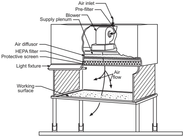
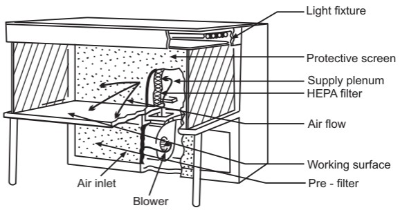
Laminar air flow equipment can deliver clean air in a vertical, horizontal, or curvilinear direction. The construction and directions of a vertical and horizontal laminar airflow bench are shown in Figures 1 and 2 respectively. The air filtered from laminar airflow is claimed to be 99.97% free from microbial contamination. This level is based upon the removal of dioctyl phthalate (DOP) particles of size 0.3 µm and larger. Air velocity at all parts of the filter should be 90 ± 20 feet/min (0.54 m/sec.)
Air Supply
The air supplied to a clean room must be filtered through high-efficiency particulate air (HEPA) filters. The HEPA filter must be positioned at the inlet for the clean room and the prefilter may be fitted upstream of the HEPA filter to prolong the life of the final filter. In these HEPA filters, pleated fiberglass paper is used as the filter medium. The filter consists of a continuous sheet of filtration material, pleated with a corrugated separator placed between each pleat and sealed into a rigid metal frame. Aluminum foil is used to form spacers in the HEPA filter.
Quality control procedures must be adopted to evaluate and monitor the quality of the HEPA filter. These filters are supported to provide class 100 air and they should be certified after every 6 to 12 months. Air quality is evaluated using settle plates, microbial air samplers, and particle counters. The velocity of HEPA-filtered air is measured using an air velometer. The efficiency of the filter in removing particulate and microbial contamination is evaluated by employing the dioctyl phthalate (DOP) test.
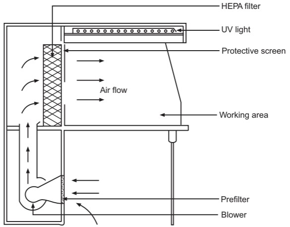
This is a universally acceptable challenge test for HEPA filters. Dioctyl phthalate smoke is introduced at the supply plenum and a photometer probe scans the surface of the filter for smoke particles. Dioctyl phthalate is a volatile liquid and under pressure, it converts to vapor or smoke having a size range of 0.3 to 0.4 µm. Leakage of the filter will permit the dioctyl phthalate particles to escape and this will be detected by the photometer. Sensors are fitted upstream and downstream of the filters to indicate the pressure differential across the filter. An alarm system should be used to indicate failure in the air supply or filter blockage. The direction of airflow in a horizontal laminar airflow is shown in Fig. 3.
Airflow Pattern
The airflow pattern within the clean room must be carefully regulated to avoid generating particles from the clean room floors, walls, and operators. The general airflow patterns in clean rooms are unidirectional airflow, non-unidirectional airflow, and combination airflow.
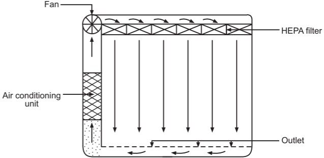
Unidirectional airflow: The air within the room moves with uniform velocity along parallel flow lines. Air enters the room through a bank of filters and exits through a bank of outlets comprising the opposite wall or floor (Fig. 4). The velocity of the air is about 0.3 m/s in downflow air from ceiling filters and 0.45 m/s in cross-flow air. These are highly efficient airflow systems but expensive to construct. Because of operating costs, unidirectional airflow clean rooms are not often used in pharmaceuticals.
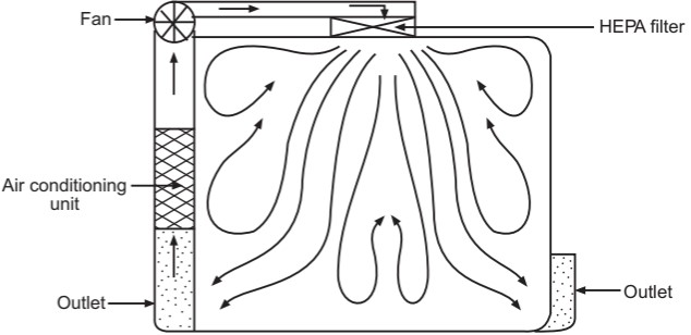
Non-unidirectional airflow: The air enters the clean rooms through filters and exits through outlet ducts, positioned low down on the wall or the floor at sites remote from the air inlet (Fig. 5). The filtered inlet air mixes with and dilutes the contaminated air within the room. Conventional airflow is defined in terms of the number of air changes per hour (≤ 20 air charges/hour).
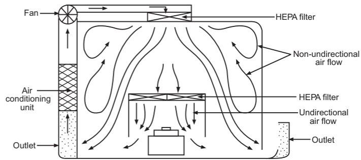
Combined airflow: In many pharmaceutical clean rooms, the background area is ventilated by a non-unidirectional airflow, and critical areas are supplied with unidirectional airflow (Fig. 6). Various vertical unidirectional airflow systems are used in combination clean rooms. There has been a trend towards protecting the critical procedures within combination clean rooms by using isolator cabinets.
The temperature and humidity are adjusted to suit the procedures being carried out within the clean room. A temperature of about 20 to 22 oC with a relative humidity of about 35 to 50% is often preferred.
Make sure you also check our other amazing Article on : Sterility Test in Microbiology